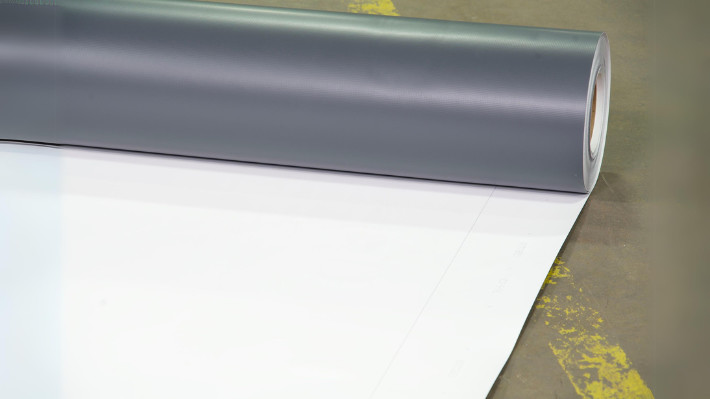
TPO Roofing Systems
- Family Description
-
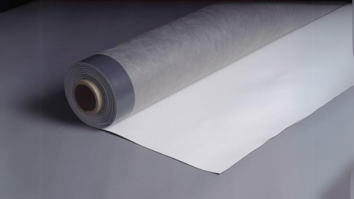
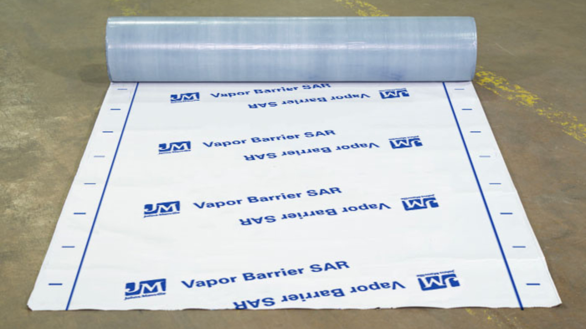
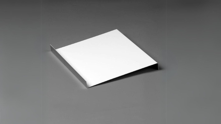
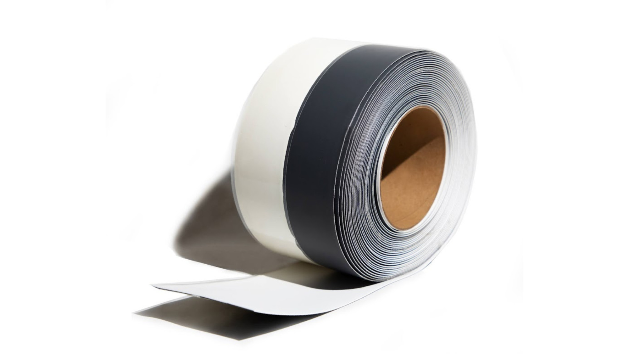
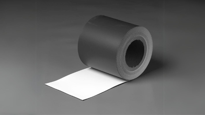
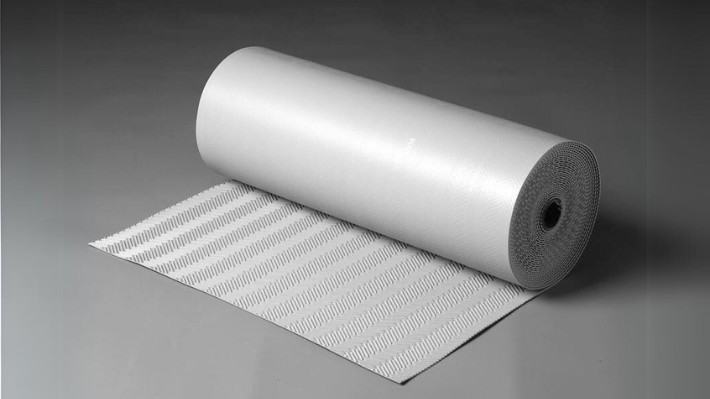
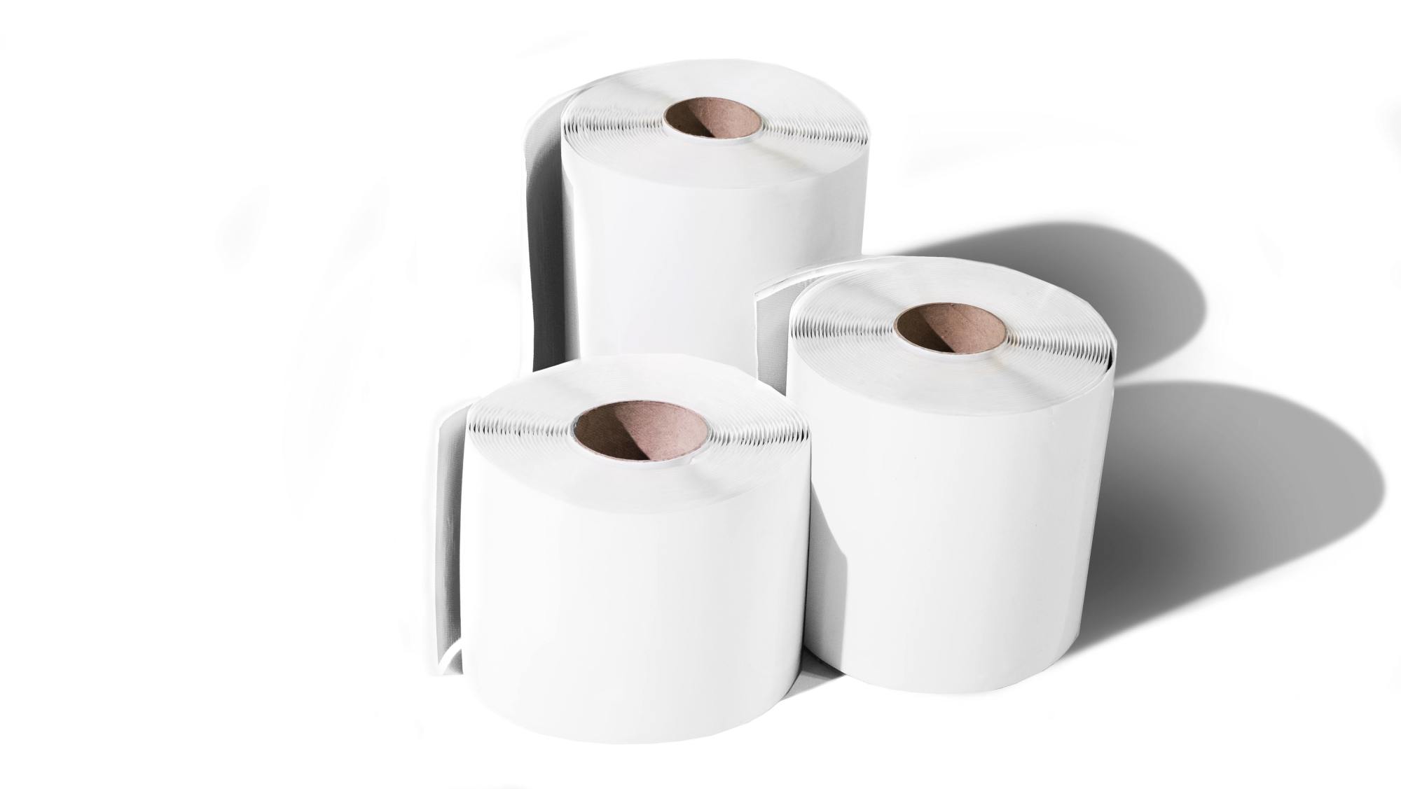
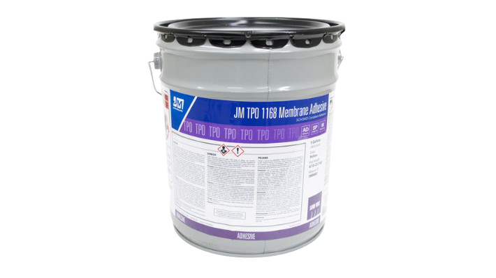
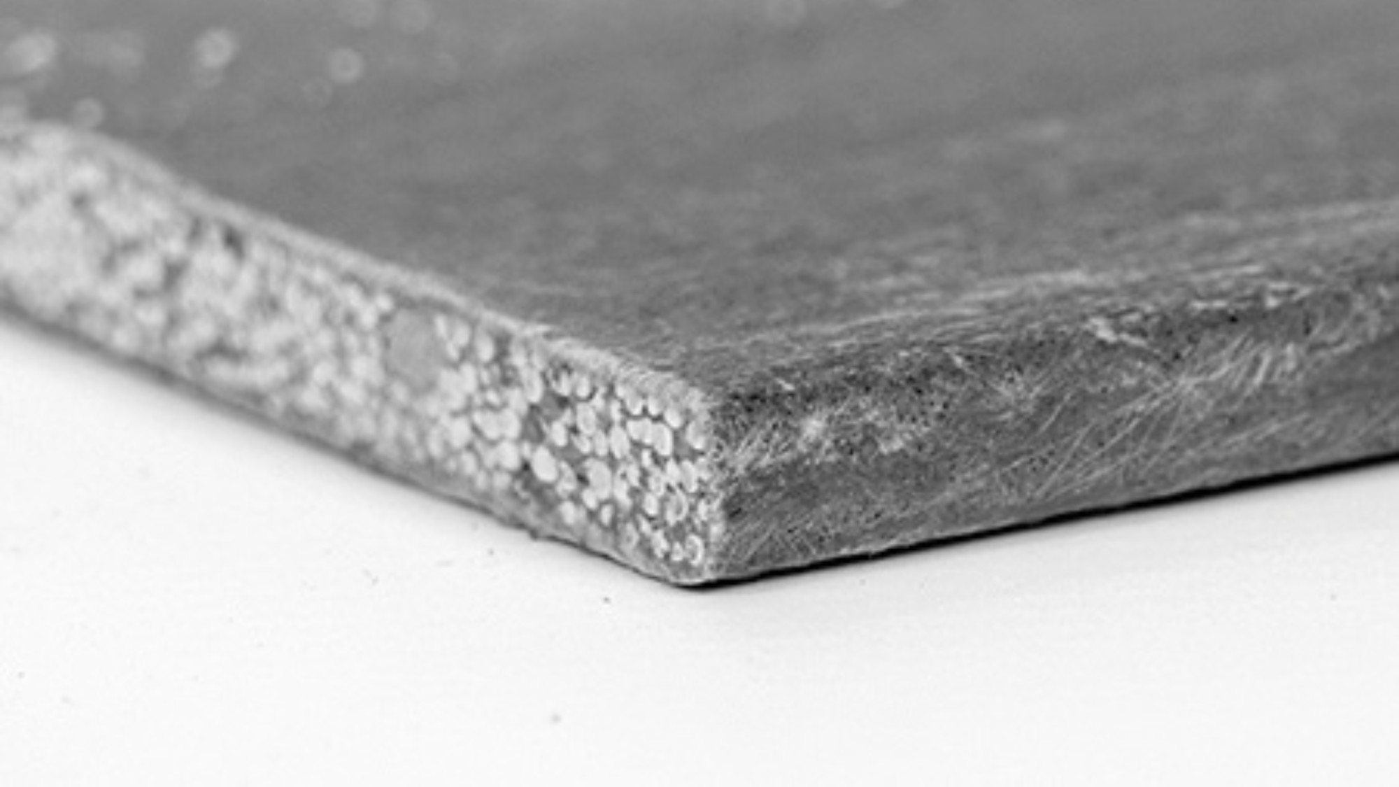
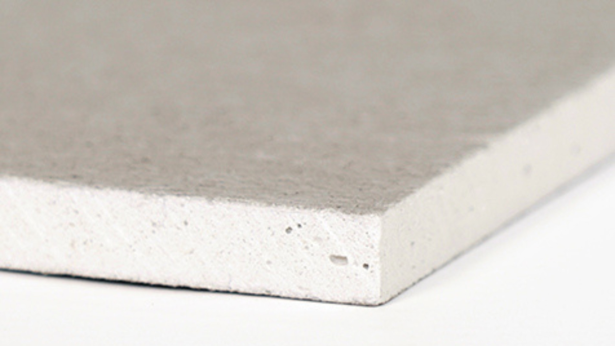
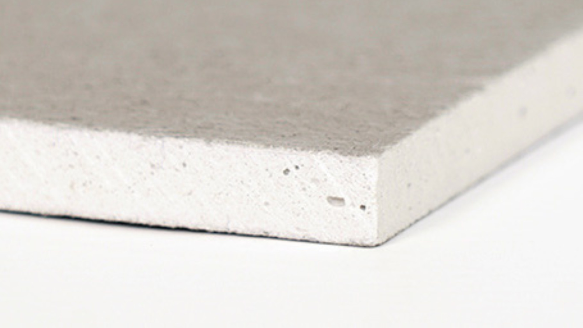
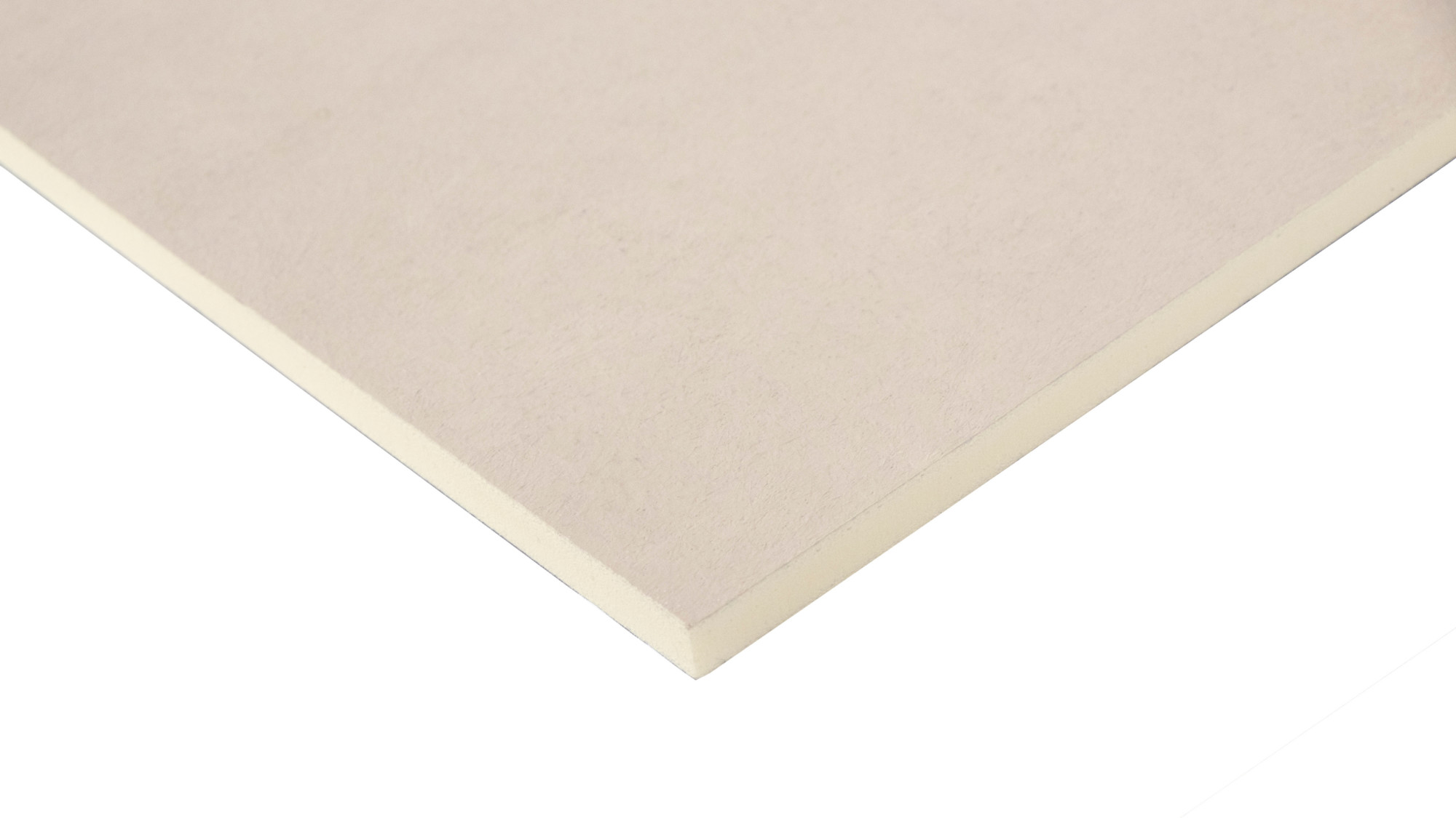
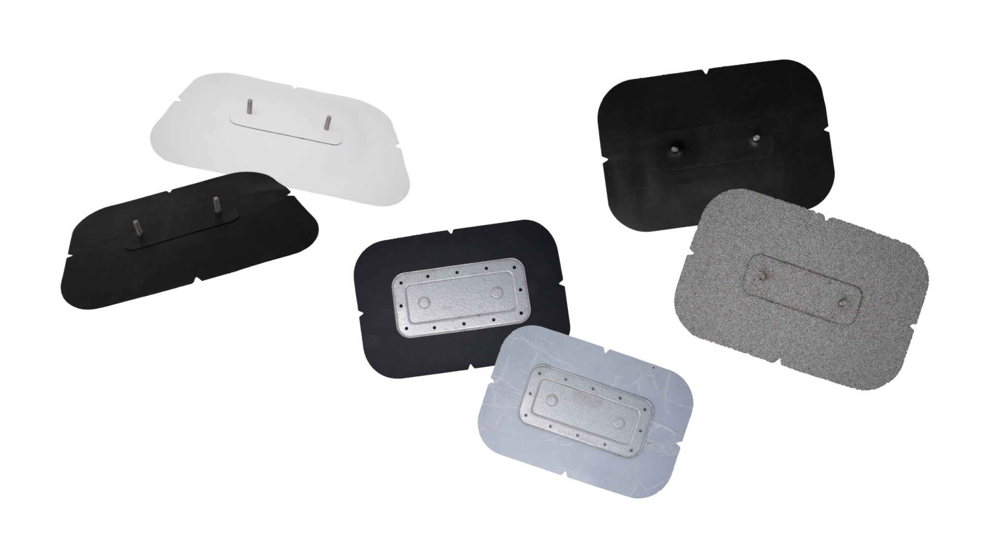
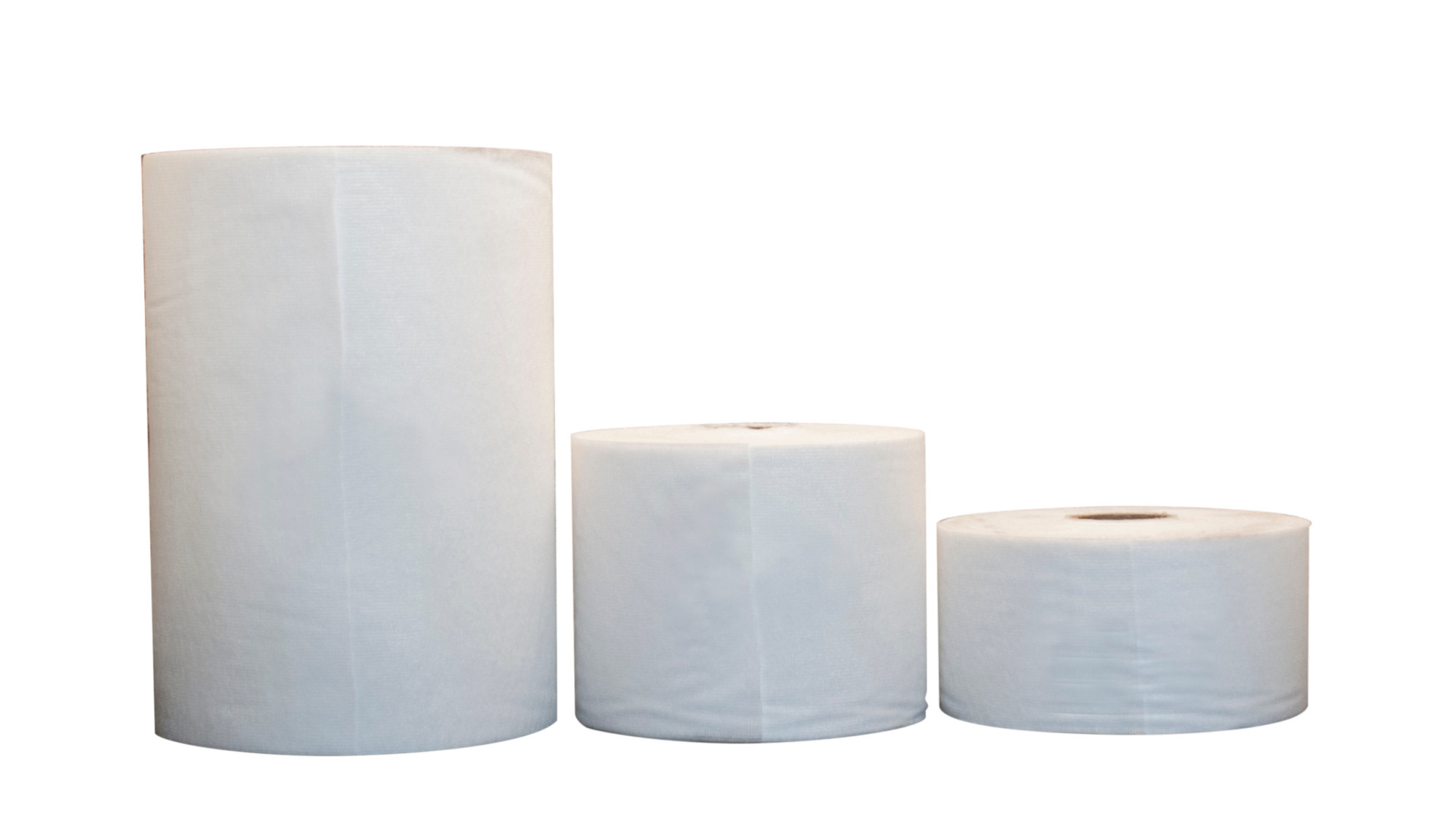
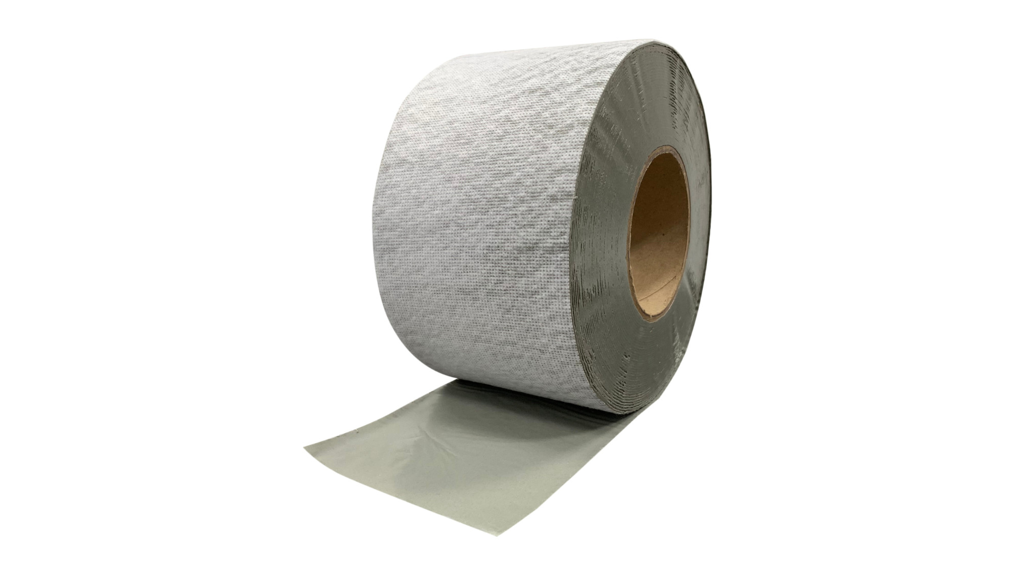
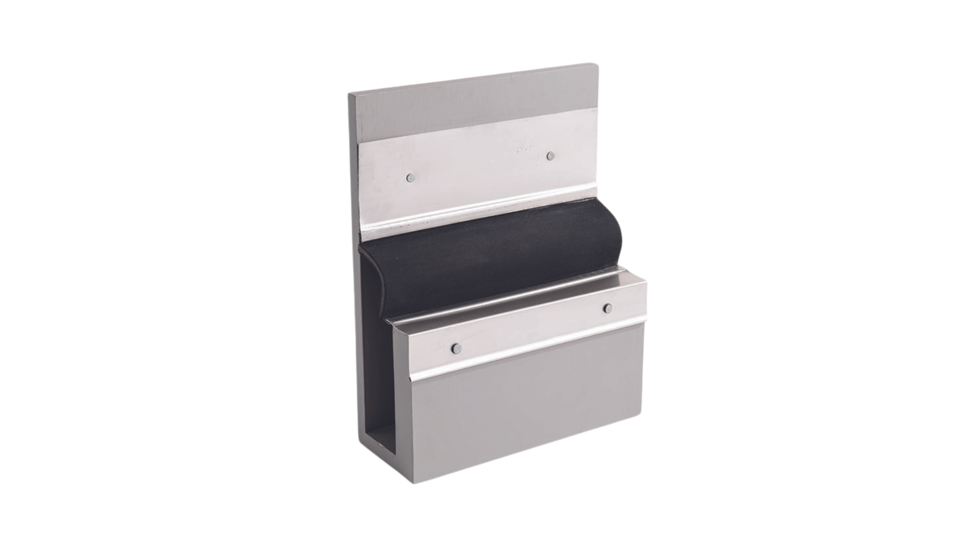
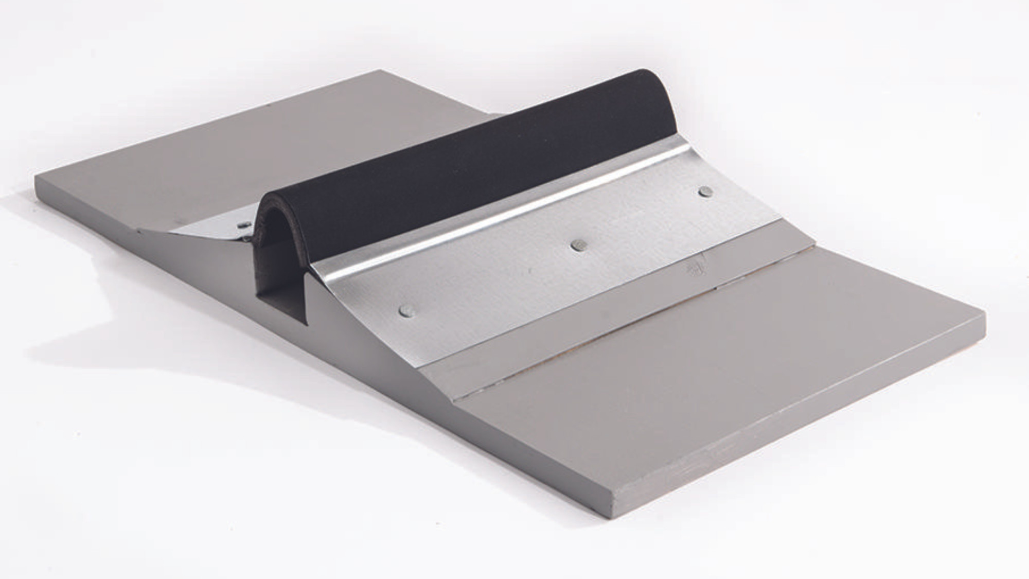
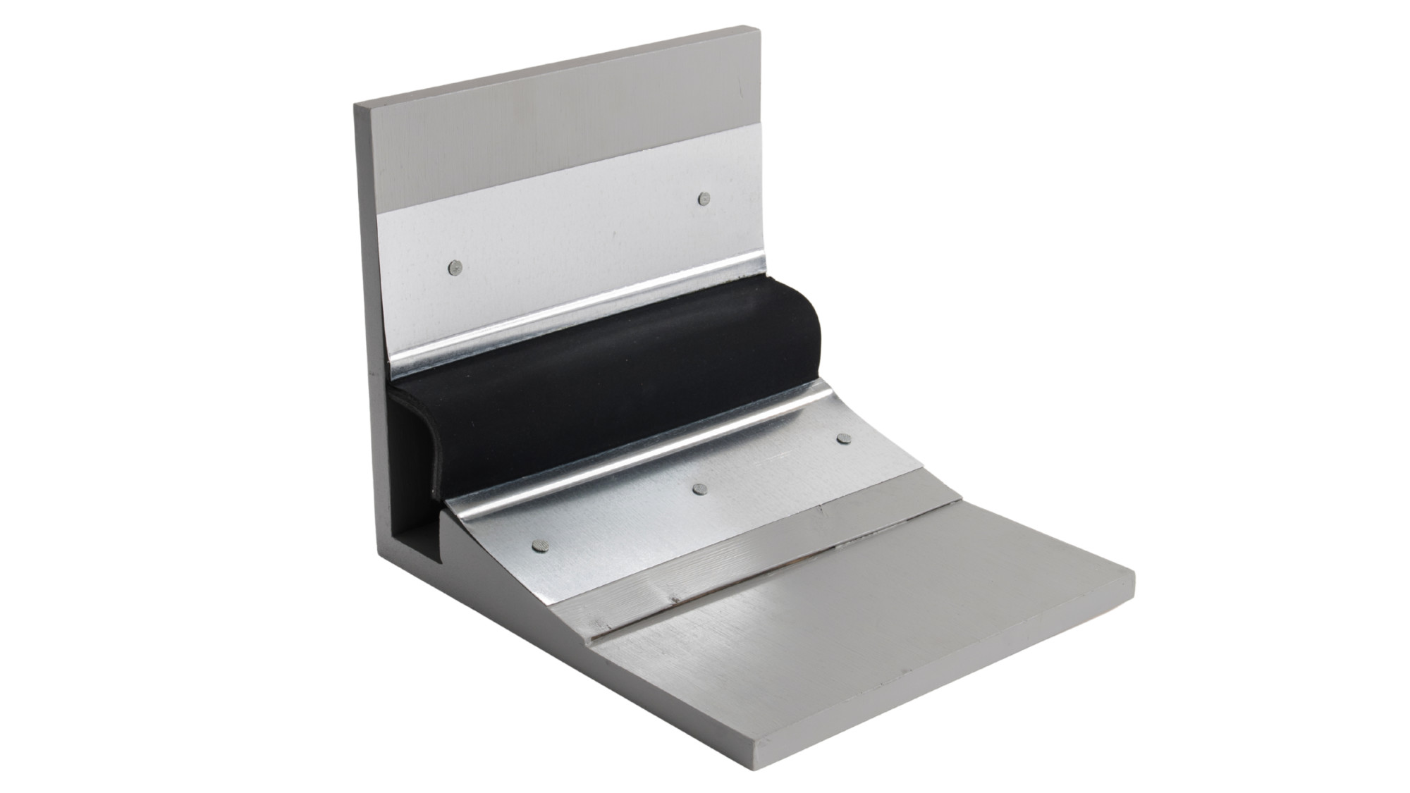
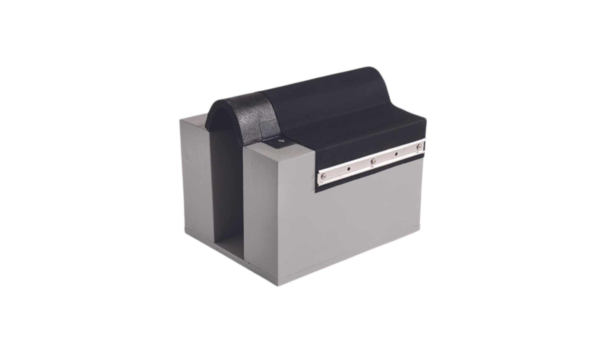
Our JM TPO roofing systems give you the option of a reliable, cost-effective roofing solution.
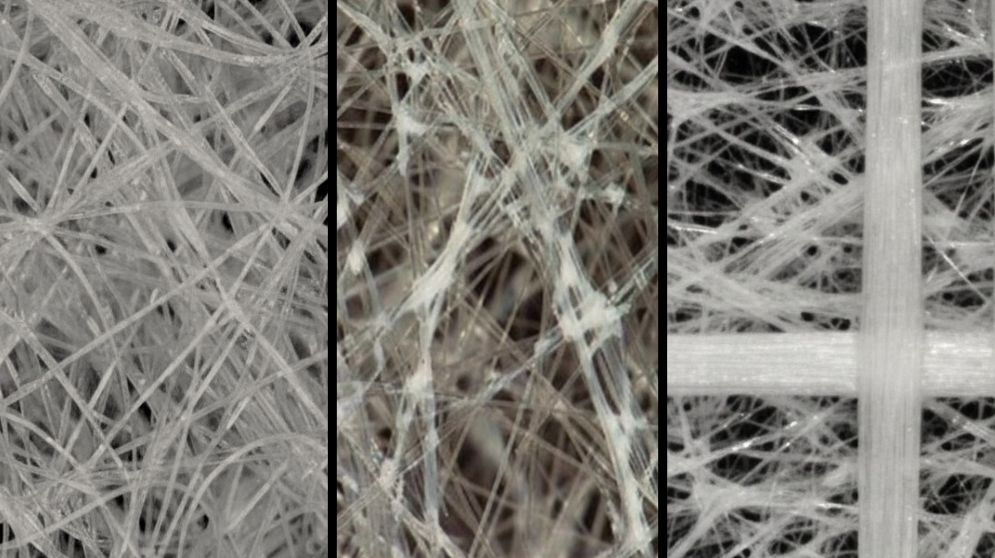
We reinforce our membranes with a polyester fabric and manufacture them using an ultraviolet-resistant thermoplastic polyolefin formulation.
We developed our TPO formulation to allow for extreme pliability, flexibility and weldability during the installation.


.png)